
ASSIGNMENT - make an in-circuit programmer
Unfortunately I was unable to complete the weeks assignment as we have not yet received our materials and components. This week will be available as soon as possible.
FABISP UPDATE {CRYSTAL}
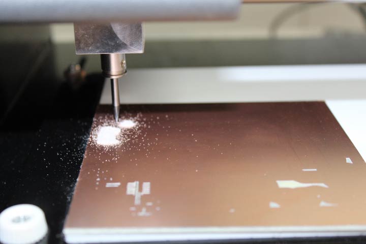
We used UBUNTU fab modules to mill the boards on the modela, using the kokompe tutorial/instruction and fabacademy fabmodules tutorial for installing and updating.
We downloaded the FAB ISP file for crystal (traces, interior) , thinking we had the correct crystals, but it turned out we did not.
Set up the fab modules to run the modela with settings for milling and after that cutting.
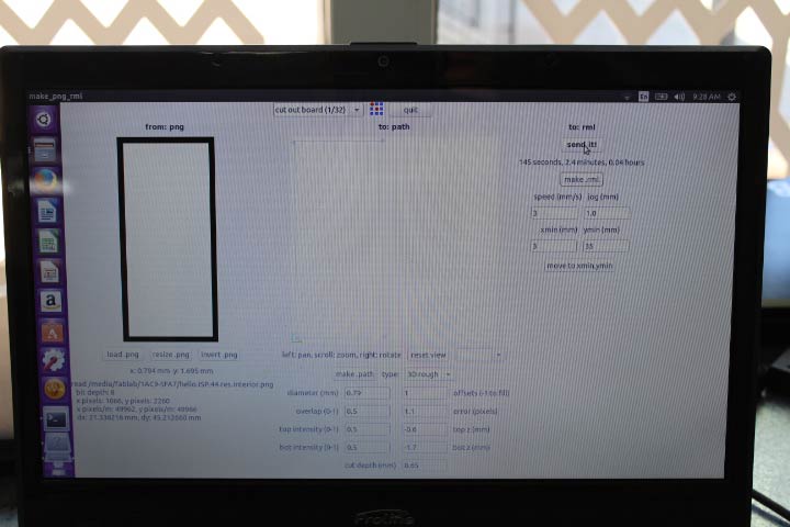
Open the modules with the command $sudo fab in the terminal on LINUX (Ctrl+Alt+T). INPUT FORMAT:image.png OUTPUT PROCESS:Roland MDX-20 mill (.rml) WORKFLOW:make-png-rml (click on make_png_rml)
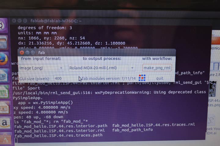
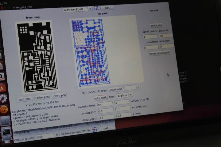
Most of the settings are automatically generated once you set the drill bit and function. To start use the 1/64 bit to mill the traces. then upload the .png in our case the hello.ISP.44.traces.png. After this you set your x and y min as part of zeroing the machine.
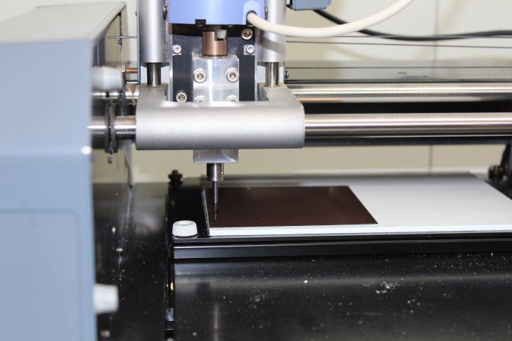
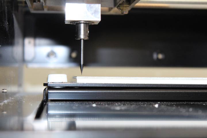
First set up the Modella by placing a sacrificial layer, in our case perspex, this will protect the plate when cutting through the PCB board.
Clean the PCB board with pure alcohol. With double sided tape, stick your PCB board onto the the sacrificial layer as close to the zero,zero x,y axis as you can.
.jpg)
Start the modella and push the view button.
Then go back to the screen and set up your x and y min to where you want the modella to zero. In our case we used 5,5. click on the move button.
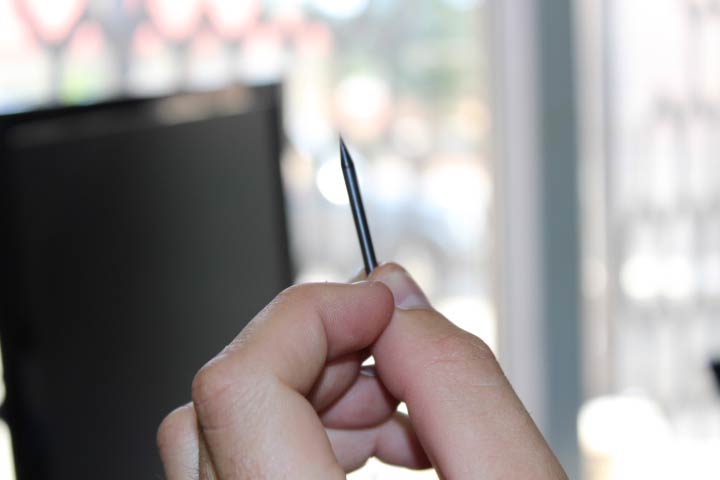
This moves the machine to 5,5 once this is completed loosen the screws at the base of the z axis arm. place the correct bit quite high in the modella and tighten the screws again. Now lower the z axis with the down button on the modella. Once at the correct height stop and then loosen one of the screws again and allow the bit to drop carefully onto the PCB board.
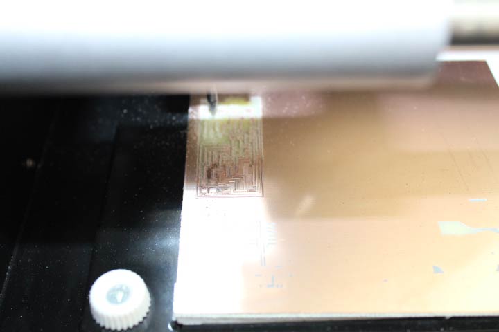
Now check that the settings are what you need. We tested quite a few variants before we finally got it to mill properly and at times needed to do double passes where the board was not perfectly flat or warped.
We started with offset 4, which did very little and ran through a whole bunch of settings on the offset from 12 throught to -4. I realised that we needed to set the z axis rather than the offset the first round was done at -0.5 which broke the tip but then we tried -0.2 and that seemed to work quite well.
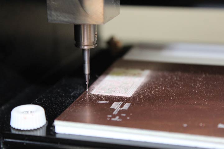
Make path>make rml>send it>begin milling
Then set up for the cut out. Set the bit to 1/32 cut out. this changes the 3D plane to 3D rough. Load the hello.ISP.44.interior.png.
Keep x,y min the same, push move and redo steps for changing the bit to a 1/32 piece. We used the generic settings.
Make path>make rml>send it>begin milling
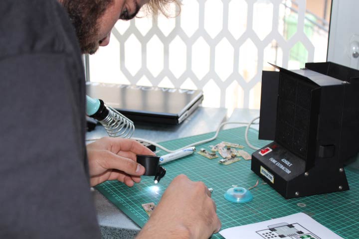
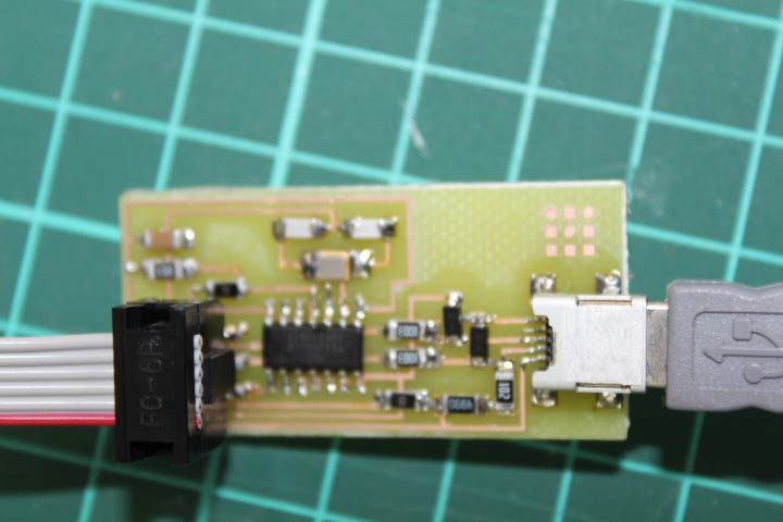
I soldered my ISP starting with the ATtiny44 - I was afraid to start with the very small USB, and felt that if I could get a feel for the soldering that might work better. The ATtiny went well and I did the USB next. and then moved around the board from the middle out as suggested. I did a lot of blobs and tinning on the smaller bits to solder as evenly as possible.
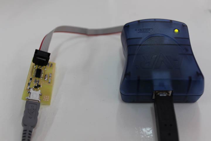
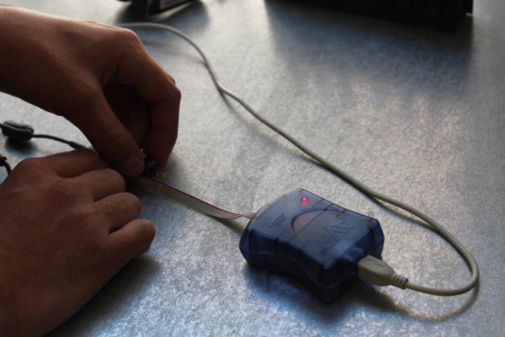
I plugged it into the AVR and I was quite lucky as my light went green first time. BUT AS STATED PREVIOUSLY WE COULD NOT PROGRAMME THEM BECAUSE THE CRYSTAL HAD 4 FEET INSTEAD OF 2.
FABISP RESONATOR {GROUP WORK}
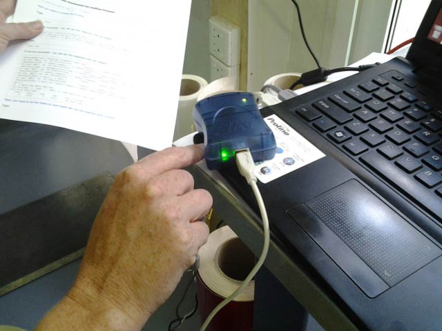
We are still awaiting crystals which have been ordered but Bjorn found an old ISP with a resonator on. So Ohad our GURU instructed that we do a group assignment to have at least one working ISP.
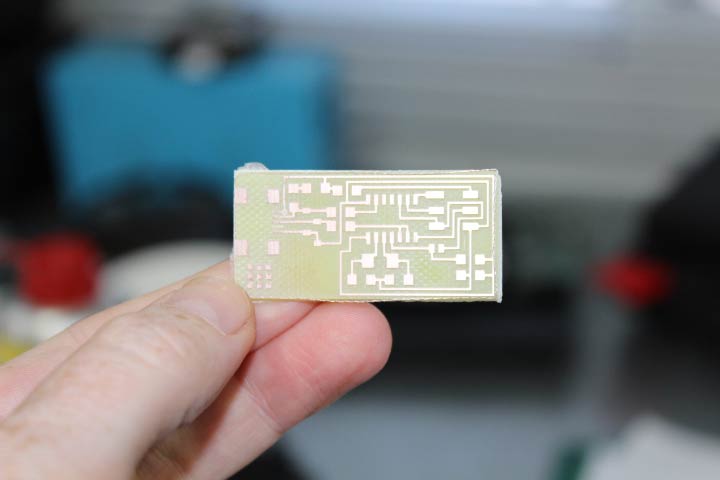
We downloaded the FAB ISP file for resonator (traces, interior) , we milled it out using similar settings as before, we had to mill it twice due to warping.
Open the modules with the command $sudo fab in the terminal on LINUX (Ctrl+Alt+T) $ fab. INPUT FORMAT:image.png OUTPUT PROCESS:Roland MDX-20 mill (.rml) WORKFLOW:make-png-rml (click on make_png_rml)
We again used the 1/64 bit to mill the traces. then uploaded the .png hello.ISP.44.res.traces.png. After this we set x and y min to 35 and 3 respectively using the top half of an old board, as part of zeroing the machine.
We set up the sacrificial layer, cleaned the PCB board with pure alcohol, and secured it to the sacrificial layer with double sided tape. Started the modella and push the view button. Then back to the screen and clicked the move button. Inserted the correct bit and zeroed it on the PCB.
We double checked the settings and used the automatic settings but changed the offset to -2 and the z to -0.2. On the second pass we set the z to -0.3.
Make path>make rml>send it>begin milling
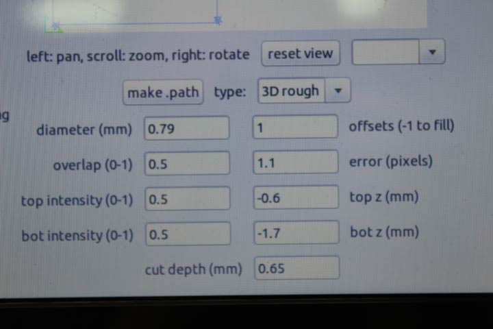
We then set up for the cut out. Set the bit to 1/32 cut out. this changes the 3D plane to 3D rough. Load the hello.ISP.44.res.interior.png.
Keep x,y min the same, push move and redo steps for changing the bit to a 1/32 piece. We used the generic settings, except for the cut depth which we made 0.65 to ensure it cut through.
Make path>make rml>send it>begin milling
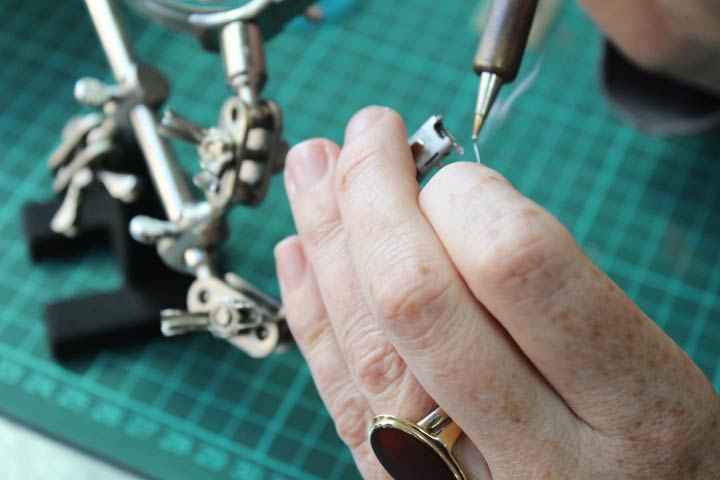
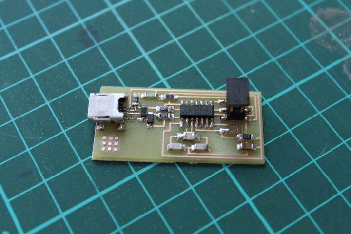
I soldered the ISP, everything went well except for the resonator which I could not get right, which Bjorn then helped with, all well until the end, I had to desolder the USB small feet, and I ripped up the copper. So Bjorn did another mill and finalised the soldering.
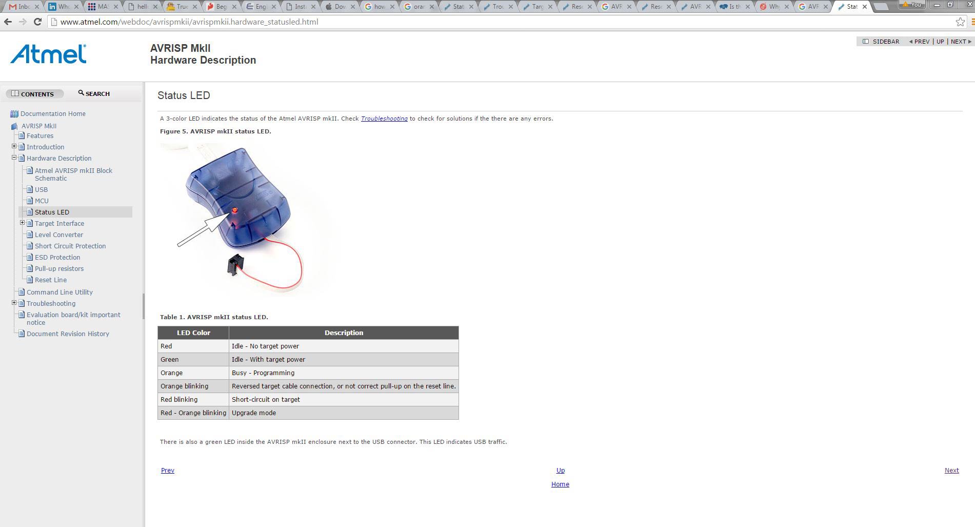
We plugged it into the AVR and got orange flashing light, as this had happened to Kirstin before we assumed that the AVR head was on the worng way, but it was not. We tried to figure out the problem and saw that some people had simply ignored this and continued with the programming.
So following the FabISP Programming tutorial online we loaded the AVR and GCC software and dependencies. and went through the tutorial step by step.
We did rename the firmware file as we could not get the terminal to access it. We named it from fabisp_mac.0.8.2_firmware to simply firmware.
Then we started the make process.
$Make clean worked
$Make hex worked but had a warning about the static void.
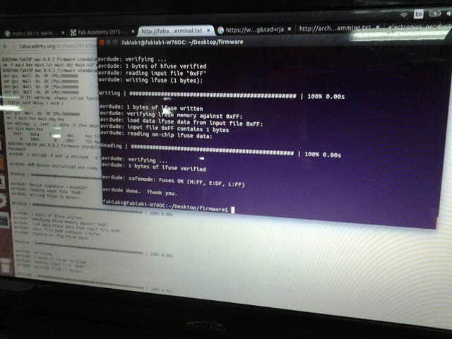
$Make fuse did not work but after a bit of internetting we found that using sudo make fuse works.
the same happened for $Make program > $sudo make program.
You can apparently use sudo from the begining.
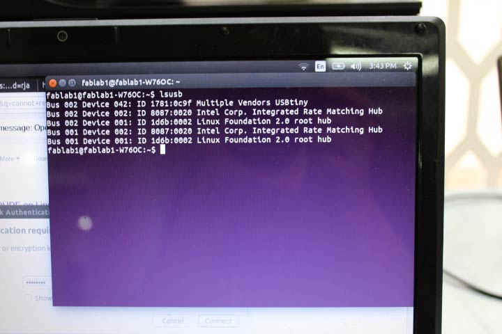
After this we struggled for some time as the instructions do not at this point indicate the solder bridge should be broken before typing $lsusb, so our USB was not reading. Kirstin then found on the internet that someone had done trouble shooting and that connection problems might be the problem, but that if it wasn't, to go ahead and desolder. Which we did.
And then reran the $lsusb and it picked up the usb as multiple vendors USBtiny. YAY!!!
Download my working files HERE